|
Brandon Dube for opticallimits.com under exclusive license
Camera lenses are wonderfully imperfect devices. Photographers will get into great debates about lens character, lens rendering and a whole host of other points of discussion. All of these things stem from imperfections (aberrations) within the optical system.
If a lens is “perfectly” corrected for all aberrations and has even transmission across the entire spectrum of interest, it is completely “transparent” and will impart no character to the image. The only limitation in a “perfectly” corrected system is how fast it is - the maximum possible resolution of a lens is determined by its f number. The lower the f number, the higher the resolution limit becomes. This limit is known as the diffraction limit, and it may be calculated in terms of the modulation transfer function via the formula below. Of course as you will see below a bigger aperture grows some aberrations so there is a “competition” at play the winner of which will be determined by the skill of the designer and constraints placed on the design.
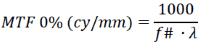
Where λ is the wavelength of light in µm. This formula will return the spatial frequency in cycles per millimeter (lp/mm) at which the MTF is 0%. 0% MTF corresponds to zero contrast and means that a transition from 100% intensity to 0% intensity – white to black – will be rendered as 50% gray and it will be impossible to tell the two apart. For diffraction limited systems, the MTF decays linearly with frequency and for all systems the MTF at 0lp/mm is 100%, so a simple slope calculation may be used to extrapolate for other frequencies. It should also be clear that the diffraction limit is higher for shorter wavelengths, this is why photolithographic lenses used to print circuits as fine as 20nm or so (currently as of April 2015) are using extreme UV light at 190nm as a source. Figure 1 is a plot of the diffraction limit of several f numbers vs spatial frequency for .5876µm green-yellow light.
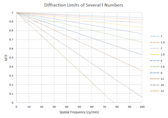
Figure 1 - Diffraction Limit vs f Number
As you can clearly see, the resolution limit decreases as the lens speed decreases. All drops in MTF from the diffraction limit are the result of aberrations.
There are many aberrations, and they may be expressed as a power series expansion, this expansion is known as the Seidel Polynomial. In their Seidel form, aberrations chiefly have two dependencies; on field, the position within the field of view/image height, and on ray height at the lens. Ray height at the lens is simply how far away from the optical axis a ray intercepts the lens. Figure 2 shows the difference between the two. Table 1 shows third order aberrations vs their dependencies where y is the ray height and h is the image height. Petzval is a way to look at field curvature.
 Figure 2 - Red varies ray height while green varies image height or field
| Aberration
|
Exponents
|
| Spherical
|
y3
|
| Coma
|
y2 h
|
| Astigmatism
|
y h2
|
| Petzval (*)
|
y h2
|
| Distortion
|
h3
|
Table 1 - Dependencies of Third Order Seidel Aberrations
(*) Petzval is equivalent to refocusing the lens, but it varies with field where refocusing does not.
From this table some facts about third order terms should become obvious:
- Spherical aberration does not change as you move in the field of view of the lens
- Distortion is not affected by stopping the lens down
- Stopping down will not be very effective in reducing astigmatism or petzval
Third order aberrations are sufficient for characterizing systems that have low étendue. Étendue is the measure of how much light passes through a system. An 800mm f/5.6 full-frame lens has very low étendue while a 14mm f/2.8 full-frame lens has very high étendue.
It does not take very long for third order aberrations to become insufficient for describing a lens well. Once they become inadequate, fifth order terms must be seriously considered. Beyond that exist seventh and ninth order terms, and so on. Typically these terms are very small and may be safely ignored. Table 2 is equivalent to table 1 but covers fifth order aberrations.
| Aberration
|
Exponents
|
| 5th-order spherical
|
y5
|
| Linear coma
|
y4 h
|
| 5th-order astigmatism
|
y h4
|
| 5th-order Petzval (*)
|
y h4
|
| 5th-order distortion
|
h5
|
| Oblique spherical
|
y3 h2
|
| Elliptical coma
|
y2 h3
|
Table 2 - Dependencies of Fifth Order Seidel Aberrations
The only terribly significant change is the addition of oblique spherical, which depends on both ray intercept height and field. Elliptical coma is a new type of coma, but looking at the exponents one could correctly guess that it looks like a “pinched” coma and is simply a thinner radial streak. All other terms have simply picked up higher powers. It should also still be apparent that spherical aberration is the only aberration that exists on-axis (in the center of the lens). All other aberrations are forbidden by symmetry.
When one moves away from the optical axis, several aberrations begin interacting and the equation becomes more complex. For example, under corrected third order spherical aberration and under corrected third order coma stack and result in large blur in the right hand side of the lens’ pupil, but in the left hand side of the pupil they mostly cancel out and only a small defocus remains.
It should be noted that the above equations are for the transverse plane only. They describe the focusing error perpendicular to the optical axis; when one refocuses a lens and produces “bokeh balls” the ball grows in the transverse plane. For the remainder of this article we will largely look at ray aberration plots also known as transverse ray plots, rim ray (RIM) plots,or H’-tan(U’)curves.
Figures 3 through 6 are ray aberration plots for various aberrations in isolation. Figures 7 through 9 are for various aberrations combined in equal quantities.
Some explanation of the plots is no doubt needed. The intersection between the horizontal and vertical axes is a ray traced through the center of the lens’ exit pupil to the image plane. If it misses, pupil aberrations are present but they are a topic for another time. To the right and left you have rays traced in the upper and lower sides of the pupil, respectively. There is consistent sign convention with a ray missing “higher” having a positive sign and a way missing “lower” having a negative sign, so it is expected for spherical aberration, which produces a circular blur, to have rays miss in opposite directions (thus, tracing out a circle). Axial chromatic aberration occurs where the different wavelengths meet at the origin of the plot (i.e. forming an X) but have different slopes, while lateral chromatic aberration occurs when they do not cross at the origin.
Please click on the images to enlarge them in a separate window!
 Figure 3 - Pure 3rd Order Spherical Aberration
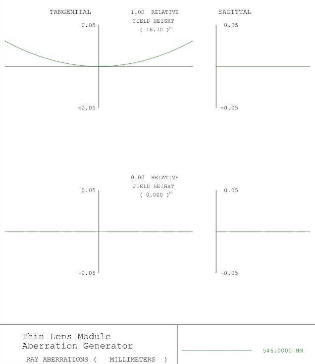 Figure 4 - Pure 3rd Order Coma
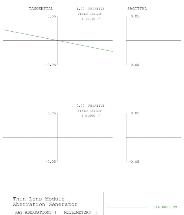 Figure 5 - Pure 3rd Order Astigmatism
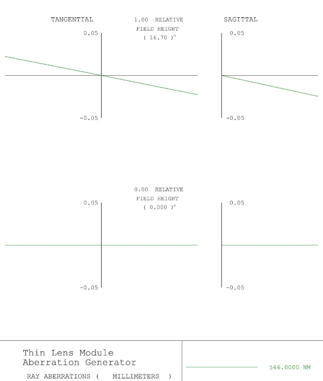 Figure 6 - Pure 3rd Order Petzval
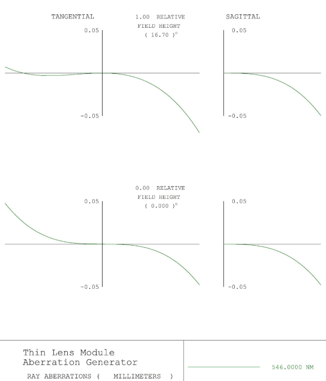 Figure 7 - Spherical Aberration + Coma
 Figure 8 - Spherical Aberration + Astigmatism
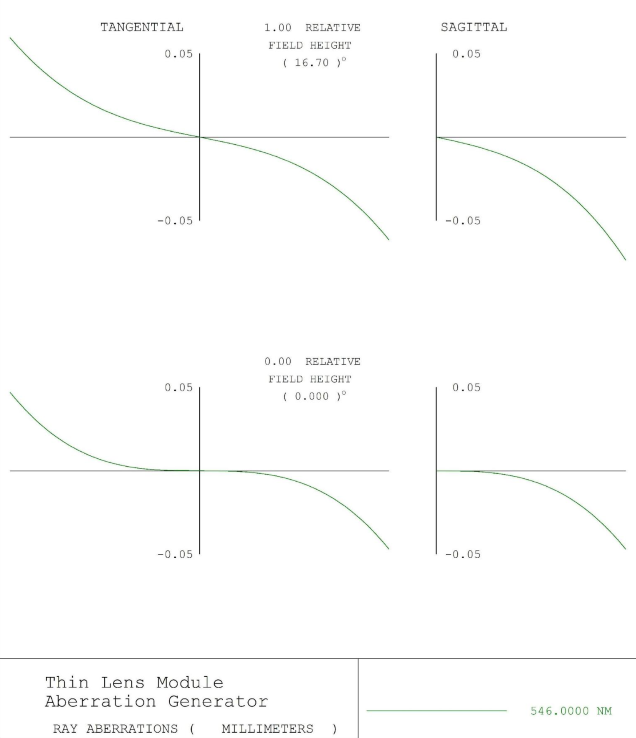 Figure 9 - Spherical Aberration + Petzval - notice difference in sagittal plane compared to Astigmatism
Aberration balancing is one of the key methods of correction in lens design. It is often impossible to correct third, fifth, and higher order aberrations to a high enough level to meet design criteria so instead they are pitted against each other. For example, it is common to be unable to correct the fifth order spherical to a satisfactory level so instead overcorrected third order spherical is used to balance it. In this way the spot size is reduced and thus the MTF (resolution) increases, despite the lens still having a complex balance of residual aberrations.
The reference plane may be moved by refocusing the lens, the result is a rotation of the abscissa of the plot and may improve the performance of the lens, especially when spherical aberration is dominant.
|